
TM66E Modular Three-Phase UPS 10–150 kVA
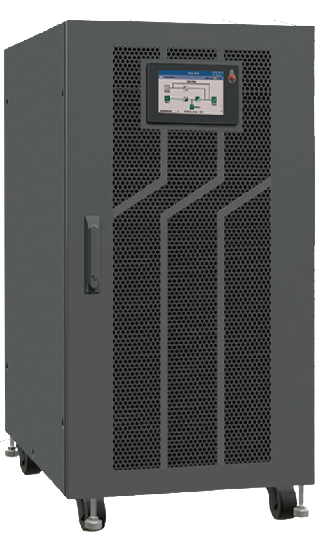
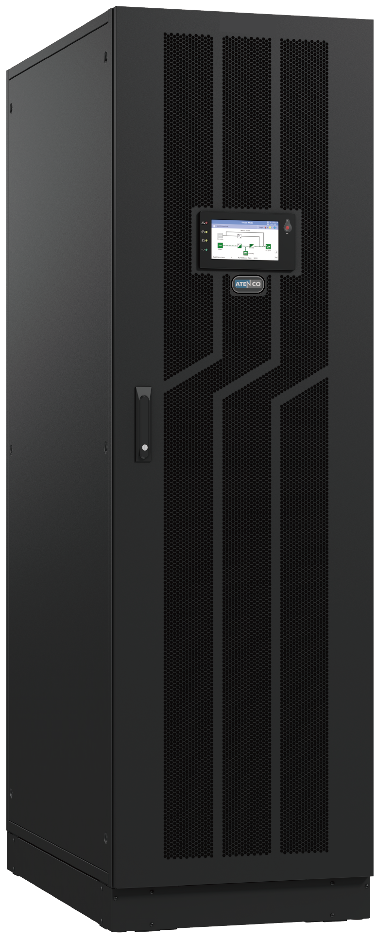
TM66E Modular 10–150 kVA is a 19″ rack-cabinet modular three-phase online double-conversion UPS for scalable data center, telecom, infrastructure and critical-power projects. It delivers output PF 1.0 with 3-level IGBT topology, dual DSP control, wide 138–485 Vac input and 0 ms AC-to-battery transfer. 10 / 15 / 20 / 25 / 30 kVA hot-swappable power modules, external VRLA battery systems, Load Bus Synchronization and N+X parallel operation up to 8 cabinets are configured by project, with a 7″ colour touchscreen.
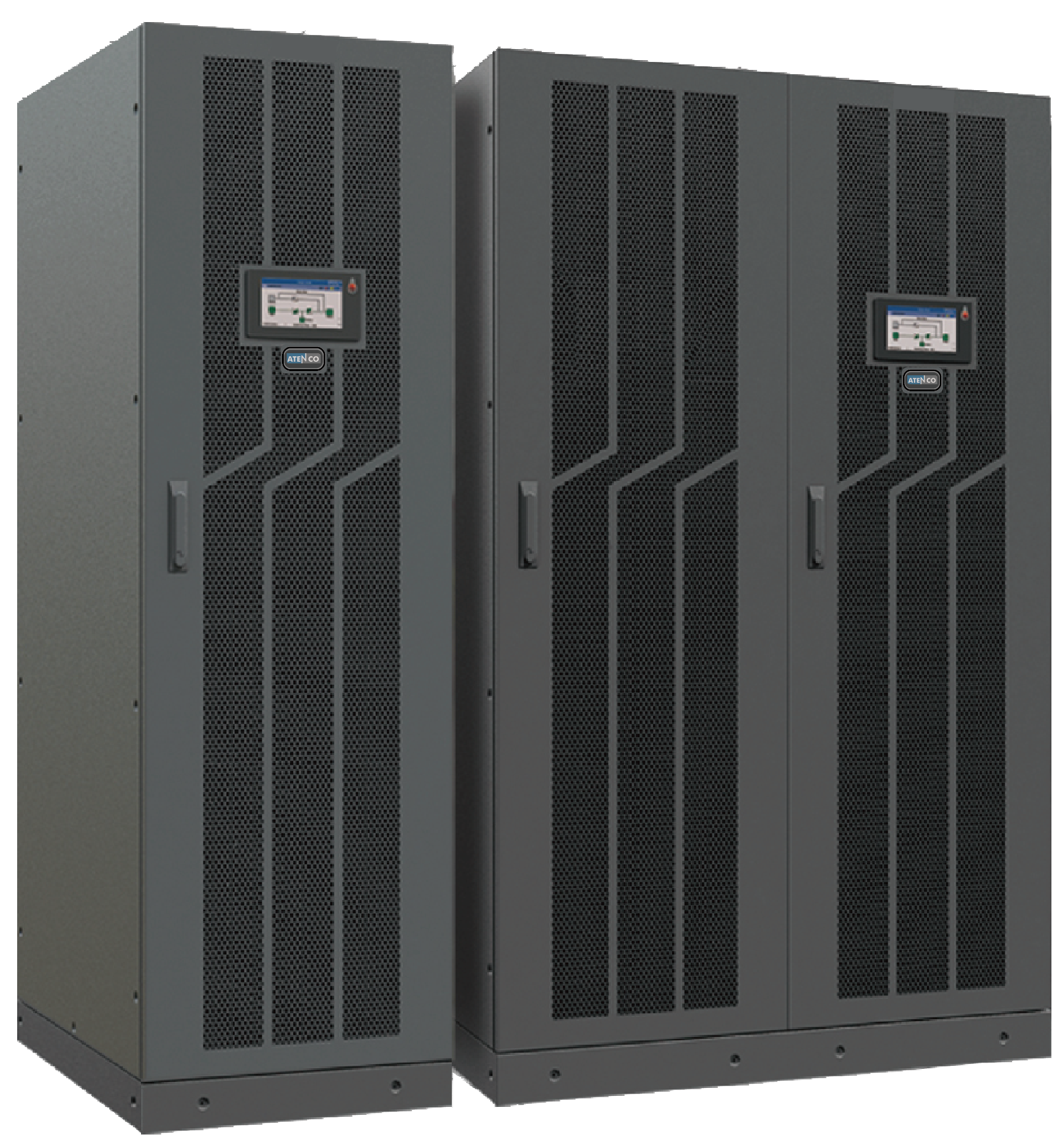
Rack-Cabinet Modular UPS with Flexible External Battery
TM66E Modular 10–150 kVA is an online double-conversion rack-cabinet modular three-phase UPS designed for scalable data-center, telecom, infrastructure and critical-power projects where external battery configuration, flexible runtime and compact rack-cabinet footprint matter. 10–30 kVA hot-swappable power modules support capacity expansion and reduced-downtime maintenance, while the external VRLA battery system enables longer runtime flexibility than built-in battery designs.
19″ Rack-Cabinet Modular Design
19″ rack-cabinet architecture with external battery system, designed for data-center rooms, network rooms and scalable modular UPS projects. The UPS cabinet uses a compact footprint without built-in battery modules, allowing runtime to be configured separately through external VRLA battery strings.
10–30 kVA Hot-Swappable Power Modules
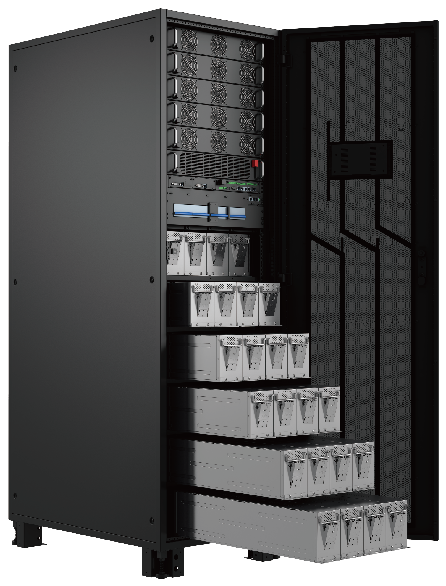
Power, bypass, monitoring and ECU control modules are hot-swappable. Power modules in 10 / 15 / 20 / 25 / 30 kVA ratings can be added, removed or replaced within cabinet capacity, supporting capacity expansion and reduced-downtime maintenance by approved procedure. Cabinet capacity scales from 10 to 150 kVA by module and cabinet configuration.
External VRLA Battery Configuration
External VRLA battery strings provide flexible runtime configuration. Battery strings can use 30–50 pcs of 12 V blocks, with programmable ±180 to ±300 Vdc battery bus by configuration. For full PF 1.0 output, 36–50 pcs are used; 32–34 pcs operate at PF 0.9 derating and 30 pcs at PF 0.8 derating. Charger current is up to 18 A.
PF 1.0 Output / 3-Level IGBT
Output PF 1.0 (kW = kVA) delivers full usable kW across the 10–150 kVA range when battery configuration supports full rating. AC-mode efficiency reaches up to 95.8% with 3-level IGBT topology. Output THDv is ≤1% with linear load and ≤3% with non-linear load. Energy-saving mode is available by configuration for stable utility conditions.
Parallel up to 8 Cabinets & LBS
Direct parallel operation supports capacity expansion or N+X redundancy up to 8 cabinets, subject to project design. Load Bus Synchronization (LBS) supports dual-bus or coordinated multi-system critical-power architectures. Shared-battery parallel configuration is supported by configuration.
Dual DSP / SNMP / RS485 / BMS
Dual DSP control supports reliable operation and system control. 7″ colour touchscreen is standard, with 10″ optional by configuration. Communications include SNMP, RS-232, RS-485, dry contact, BMS, EPO and REPO by configuration. Power Walk-In limits start-current impact for generator-backed sites when the generator is properly sized and configured.
Expand Your TM66E Modular 10–150 kVA System
Optional accessories for TM66E Modular 10–150 kVA include external VRLA battery systems, hot-swappable power modules, parallel kit with LBS, TM550 SNMP card, relay / dry-contact interfaces and external maintenance bypass – specified according to UPS capacity, runtime target, redundancy plan and project design.
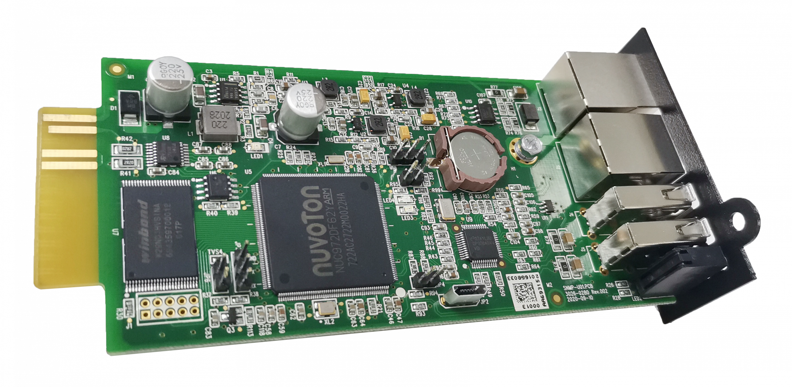
TM550 SNMP Network Card
Optional TM550 SNMP card fits the intelligent slot and enables network monitoring, web access, event alerts, shutdown management and NMS / BMS integration. RS-485 / Modbus RTU supports BMS / SCADA integration by configuration.
Parallel Kit / LBS Synchronization
Parallel kits support capacity expansion and N+X redundancy up to 8 cabinets by configuration. Load Bus Synchronization (LBS) supports dual-bus or coordinated multi-system designs for critical-power architectures.
External VRLA Battery System
TM66E Modular 10–150 kVA uses external VRLA battery strings for flexible runtime configuration. Battery strings use 30–50 pcs of 12 V blocks per string with programmable ±180 to ±300 Vdc bus by configuration. Battery system, runtime and temperature sensor are selected according to UPS capacity, load level and target backup time.
Technical Details
Complete specifications for the TM66E Modular 10–150 kVA rack-cabinet modular three-phase UPS platform.
| Specification | Value |
|---|---|
| Full Name | TM66E Modular Three-Phase UPS (Rack-Cabinet, External Battery) |
| Topology | Online Double-Conversion (VFI), 3-Level transformer-less, hot-swappable modules |
| Phase | 3P–3P (3Ph+N+PE in / 3Ph+N+PE out) |
| Configured Project Range | 10–150 kVA by module / cabinet configuration |
| Form Factor | 19″ rack-cabinet modular (W 600 × D 850 × H 1200 mm); external battery system |
| Power Module Sizes | 10 / 15 / 20 / 25 / 30 kVA (2U, 440 × 620 × 86 mm); hot-swappable |
| Output Power Factor | 1.0 (kW = kVA) |
| Display | 7″ colour touchscreen standard / 10″ optional |
| Battery Support | External VRLA lead-acid maintenance-free battery system; 30–50 pcs of 12 V blocks per string; programmable ±180 to ±300 Vdc bus by configuration |
| Operating Modes | Online, ECO / energy-saving, Bypass, Battery, Maintenance |
| Parallel | Up to 8 cabinets (N+X redundancy or capacity expansion); shared-battery parallel supported |
| Load Bus Synchronization (LBS) | Supported for dual-bus / synchronized multi-system designs by configuration |
| Generator Compatible | Yes – Power Walk-In limits start-current impact on generator capacity |
| Standards | IEC/EN 62040-1, IEC/EN 62477-1 safety; IEC/EN 62040-2 + IEC 61000 series EMC; IEC 62040-3:2021 performance; CE by series |
Module × Cabinet Configuration Matrix
| Power Module | Cabinet Capacity Options | Max Module Number |
|---|---|---|
| 10 kVA | 30 / 50 kVA | 3 / 5 |
| 15 kVA | 45 / 75 kVA | 3 / 5 |
| 20 kVA | 60 / 100 kVA | 3 / 5 |
| 25 kVA | 50 / 125 kVA | 2+1 redundancy / 5 |
| 30 kVA | 60 / 150 kVA | 2+1 redundancy / 5 |
Configured project range: 10–150 kVA by module / cabinet configuration. ATENCO engineers select the module size and cabinet capacity for each project per load, redundancy and runtime requirements.
| Specification | 30 | 45 | 50 | 60 | 75 | 100 | 125 | 150 kVA |
|---|---|---|---|---|---|---|---|---|
| Nominal Input Voltage | 380 / 400 / 415 Vac (3Ph+N+PE) | |||||||
| Input Voltage Range | 138–485 Vac (138–305 Vac for 40% load; 305–485 Vac for 100% load) | |||||||
| Input PF | ≥0.99 at 100% linear load | |||||||
| Input THDi | ≤3% at 100% linear load | |||||||
| Bypass Voltage Range (Max) | +25% (Optional +10% / +15% / +20%); 230 V: +20%; 240 V: +15% | |||||||
| Bypass Voltage Range (Min) | −45% (Optional −10% / −15% / −20% / −30%) | |||||||
| Bypass Frequency Range | 50 / 60 Hz ±10% | |||||||
| Output Voltage | 380 / 400 / 415 Vac (3Ph+N+PE), ±1% regulation | |||||||
| Output PF | 1.0 (kW = kVA) | |||||||
| Output THDv (linear) | ≤1% | |||||||
| Output THDv (non-linear) | ≤3% | |||||||
| Output Frequency (Line mode) | Synchronize with input; ±1% / ±2% / ±4% / ±5% / ±10% optional tracking | |||||||
| Output Frequency (Battery) | 50 / 60 ±0.1% | |||||||
| Crest Factor | 3:1 | |||||||
| Transfer Time | 0 ms AC-to-battery; automatic bypass protection by operating condition | |||||||
| Efficiency (AC Mode) | Up to 95.8% by configuration | |||||||
| Energy-Saving Mode | By configuration; available for operation in stable utility conditions | |||||||
| Specification | Value |
|---|---|
| Battery Type | VRLA (Lead-acid maintenance-free) |
| Battery Voltage / DC Bus | Programmable ±180 to ±300 Vdc, by battery quantity (±180 / 192 / 204 / 216 / 228 / 240 / 252 / 264 / 276 / 288 / 300 Vdc) |
| Charging Current (Max) | 18 A |
| Charger Type | 3-stage smart charger |
| Battery Configuration | External VRLA battery strings, 30–50 pcs of 12 V blocks per string; 36 pcs default (30 / 32 / 34 / 36 / 38 / 40 / 42 / 44 / 46 / 48 / 50 pcs by configuration) |
| Output PF Derating by Battery Count | 36–50 pcs: PF 1.0 (full); 32–34 pcs: PF 0.9 derating; 30 pcs: PF 0.8 derating |
| Battery Temp Sensor | Optional via BAT_T port |
| BMS Communication | Optional for advanced battery management |
| DC Cold Start | Supported when battery system is installed and available |
| Lithium Battery Support | Not supported on this platform; for lithium battery systems, use TM66E Modular 40–600 kVA or TM66E Large Modular 400–1200 kVA by configuration |
Exact external battery configuration (string count, blocks per string, total runtime) is sized by ATENCO engineers according to UPS capacity, load level and target backup time.
| Component | Specification |
|---|---|
| UPS Cabinet Dimensions | 600 × 850 × 1200 mm |
| UPS Cabinet Weight | 130–170 kg by model |
| Power Module (W × D × H) | 440 × 620 × 86 mm (2U) |
| Power Module Weight | 10 kVA module = 19 kg; 15 / 20 / 25 / 30 kVA modules = 21 kg |
| Form Factor | Rack-cabinet modular; external battery system by configuration |
| Protection Class | IP20 |
| Colour | Black |
Noise Levels
| Configuration | Noise (dB at 1 m) |
|---|---|
| Smaller configurations | <58 dB |
| Higher configurations | <61 dB |
Cable sizing, external breaker ratings and protection coordination must follow local electrical code, installation method, cable type, ambient temperature, grouping, voltage drop, upstream / downstream protection and project electrical design.
| Interface | Details |
|---|---|
| Display | 7″ TFT touchscreen standard / 10″ optional with mimic diagram and event history |
| RS-232 | Serial port for local monitoring software |
| RS-485 | For Modbus RTU communication and BMS / SCADA integration by configuration |
| Parallel Port | For N+X parallel operation up to 8 cabinets |
| LBS Port | Load Bus Synchronization for dual-bus / synchronized multi-system designs |
| BMS Port | Battery Management System interface |
| Dry Contact Port | Configurable contact port for status signalling |
| EPO & REPO | Standard – Emergency Power Off / Remote Emergency Power Off |
| BAT_T Port | Optional battery temperature sensor connection |
| Intelligent Slot Cards (Optional) | TM550 SNMP card (network monitoring, web access, NMS / BMS integration); relay card (dry-contact integration) |
| FW / SW Upgrade | Online upgrade in bypass mode |
| Software | Local monitoring software via RS-232 / RS-485; network monitoring via optional TM550 SNMP card |
Inverter Mode Overload
| Load Level | Duration | Action |
|---|---|---|
| ≤110% | 60 minutes | Sustained |
| ≤125% | 10 minutes | Overload protection |
| ≤150% | 1 minute | Overload protection |
| >150% | 1.2 seconds | Shut down inverter |
Bypass Mode Overload
| Load Level | Duration | Action |
|---|---|---|
| 30 °C: ≤135% | Long term | Sustained on bypass |
| 40 °C: ≤125% | Long term | Sustained on bypass |
| >1000% | 100 ms | Protection trip |
System Protection & Alarm
| Function | Behaviour |
|---|---|
| Overheat (Line Mode) | Switch to Bypass |
| Overheat (Battery Mode) | Shut down UPS immediately |
| Self-Diagnostics | Upon Power-On and Software Control |
| LCD Alarms | Line Voltage, Bypass Mode, Battery Low, Battery Fault, Overload, UPS Fault |
| Audible Alarms | Line Failure, Battery Low, Overload, System Fault |
| EPO Action | Shut down UPS immediately |
| Parameter | Specification |
|---|---|
| Operating Temperature | 0°C to 40°C |
| Storage Temperature | −25°C to 55°C |
| Humidity | 0–95% RH non-condensing |
| Altitude | <1000 m without derating; derating required above 1000 m |
| Clearance | Minimum front and rear clearance per installation manual for ventilation and maintenance |
| Safety Standards | IEC/EN 62040-1, IEC/EN 62477-1 |
| EMC Standards | IEC/EN 62040-2 (IEC 61000-2-2, IEC 61000-4-2/-3/-4/-5/-6/-8/-11) |
| Performance Standards | IEC 62040-3:2021, EN IEC 62040-3:2021 |
| Cooling | Forced air (fan); modular module cooling |
| Installation | Indoor use only |
| Applications | Data centers and core IT, network rooms and telecom switching, industrial automation and process control, security command and control rooms, commercial building critical infrastructure with capacity needs up to 150 kVA. |
Incompatible loads: This series of products is not compatible with energy-feedback loads, including but not limited to CT machines in the medical field, cutting machines in the semiconductor industry, and all types of elevators or other motor-driven equipment that incorporate energy-feedback inverters at the front end.
Ideal For
TM66E Modular 10–150 kVA is designed for three-phase critical-power sites that need rack-cabinet modular UPS architecture, 10–30 kVA hot-swappable power modules, external VRLA battery runtime and N+X scalability up to 8 cabinets. It is best suited for data-center rooms, telecom aggregation sites, network cores, industrial control rooms and critical infrastructure projects where flexible runtime and scalable modular capacity matter.

Data Center Rooms & Server Infrastructure
Rack-cabinet modular three-phase UPS protection for small to mid-size data-center rooms, server rooms, IT racks, storage systems and network cores requiring PF 1.0 output, external VRLA battery runtime and scalable N+X modular redundancy.

Network Rooms & Campus IT Cores
Modular UPS for building network rooms, campus IT cores, distribution frames, core switches, structured-cabling rooms and enterprise IT infrastructure where 19″ rack-cabinet architecture and external battery configuration simplify project deployment.

Telecom Aggregation & Transmission Sites
Three-phase modular UPS for telecom aggregation rooms, transmission sites, access-network hubs and remote communication facilities requiring external VRLA battery autonomy, Power Walk-In generator compatibility and parallel expansion by configuration.

Industrial Control & Automation Rooms
Online modular UPS protection for PLC / SCADA servers, industrial PCs, automation servers, control-room IT and instrumentation systems supplied from plant three-phase distribution – excluding regenerative or energy-feedback loads unless approved by ATENCO engineering.

Security Command & Control Infrastructure
Three-phase UPS backup for NVR / VMS server racks, access-control servers, surveillance command rooms, security network cores and control-room workstations requiring modular redundancy, SNMP monitoring and external battery runtime.

Infrastructure & Public-Sector IT Rooms
Rack-cabinet modular UPS for airport IT rooms, transport control rooms, utility communication rooms, government data rooms and public-building technical rooms where scalable three-phase backup, external battery autonomy and LBS-ready redundancy are required.
Need Internal Battery, Larger Capacity or Lithium Support?
Compare TM66E Modular 10–150 kVA with the Compact 30–75 platform with internal-battery option, the Modular 40–600 mid-range with VRLA / lithium, or the Large Modular 400–1200 flagship with HECO mode and lifecycle management.
Compact Modular UPS 30–75 kVA
Use when the project needs built-in battery modules instead of external battery cabinets.
- Modular cabinet with internal battery
- 10–30 kVA hot-swappable power modules
- Up to 6 internal VRLA battery groups
- No external battery cabinet required
- Parallel up to 6 cabinets with LBS
TM66E Modular 10–150 kVA UPS FAQ
Answers about TM66E Modular 10–150 kVA rack-cabinet modular UPS architecture, external VRLA battery configuration, PF 1.0 output, hot-swappable power modules, N+X parallel operation and Load Bus Synchronization.
What is the TM66E Modular 10–150 kVA UPS?
What is the difference between TM66E Modular 10–150 kVA and TM66E Compact 30–75 kVA?
Does TM66E Modular 10–150 kVA use built-in batteries?
Can the TM66E Modular 10–150 kVA be paralleled for redundancy?
What battery options does the TM66E Modular 10–150 kVA support?
Can the TM66E Modular 10–150 kVA run on a generator?
What monitoring options does the TM66E Modular 10–150 kVA support?
What is LBS synchronization on the TM66E Modular 10–150 kVA?
Does TM66E Modular 10–150 kVA support lithium batteries?
Is TM66E Modular 10–150 kVA hot-swappable?
Which applications is the TM66E Modular 10–150 kVA not recommended for?
Size Your TM66E Modular 10–150 kVA UPS Project
Share your three-phase load list, target backup time, redundancy plan, site voltage, generator details, external VRLA battery configuration and monitoring requirements. ATENCO will recommend the suitable TM66E Modular 10–150 kVA configuration with 10 / 15 / 20 / 25 / 30 kVA hot-swappable power modules, external VRLA battery system, parallel topology, Load Bus Synchronization (LBS) and TM550 SNMP / relay-card options matched to your project.
Send Project Requirements
Share three-phase load in kW / kVA, target runtime, redundancy requirement, site nominal voltage, generator details, external VRLA battery runtime requirement and monitoring preferences such as TM550 SNMP, RS-485 / Modbus RTU, relay card, BMS or NMS integration.
Receive UPS Selection & Sizing
ATENCO engineers recommend the suitable TM66E Modular configuration: cabinet capacity, 10 / 15 / 20 / 25 / 30 kVA power-module configuration, external VRLA battery string plan, parallel topology, LBS design and matching TM550 SNMP or relay-card accessories.