
TM33E Three-Phase Tower UPS 10–40 kVA
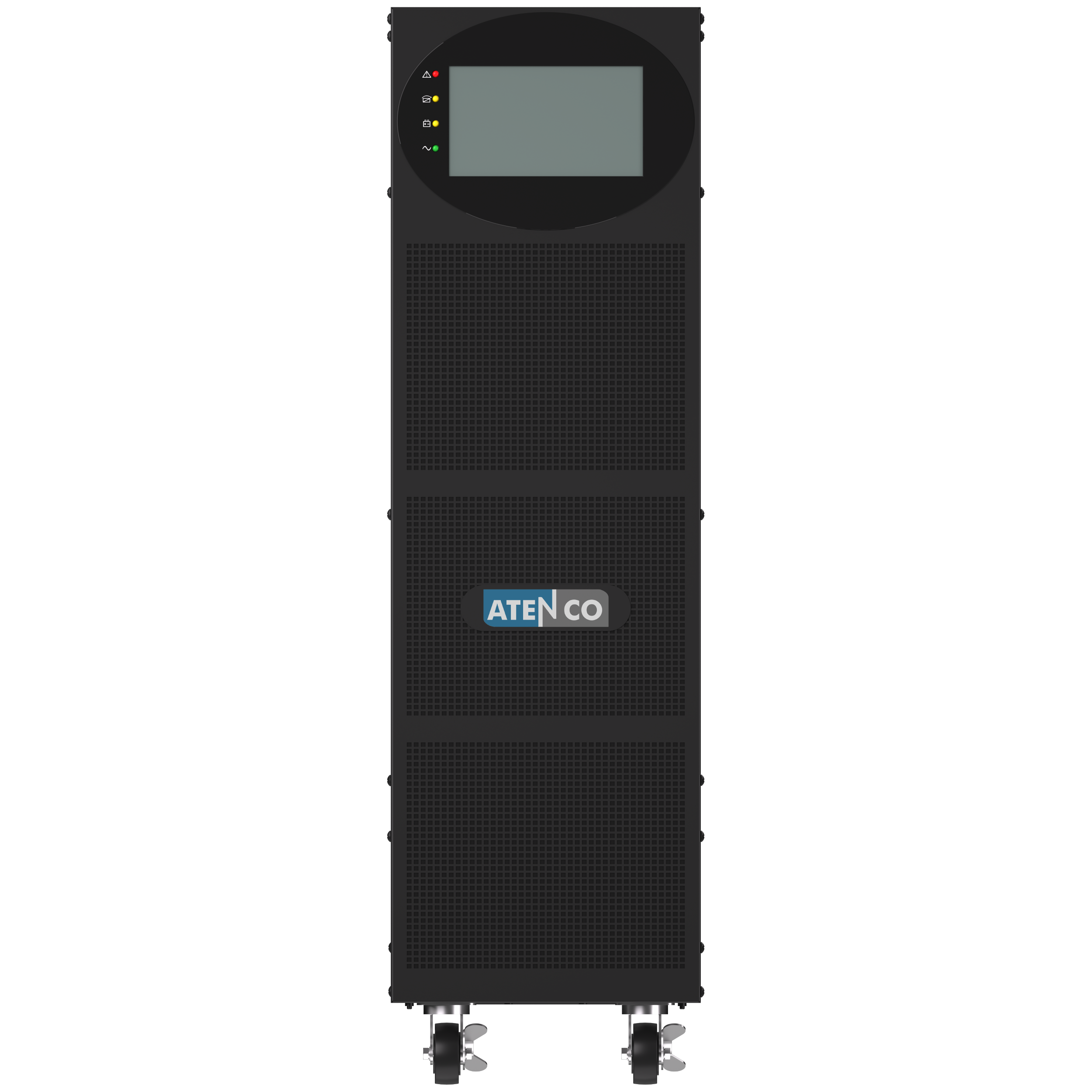
TM33E 10–40 kVA is a transformer-less online double-conversion VFI three-phase tower UPS for data centers, industrial automation, telecom, healthcare facility IT and critical infrastructure. It delivers regulated three-phase output at PF 1.0, using IGBT rectifier and inverter, DSP digital control, pure sine-wave power, wide input-voltage tolerance and 0 ms transfer between online and battery operation. Internal-battery or long-runtime external-battery variants, a 7-inch TFT touchscreen on selected models and parallel operation up to 4 units are configured by project across 10, 15, 20, 30 and 40 kVA ratings.
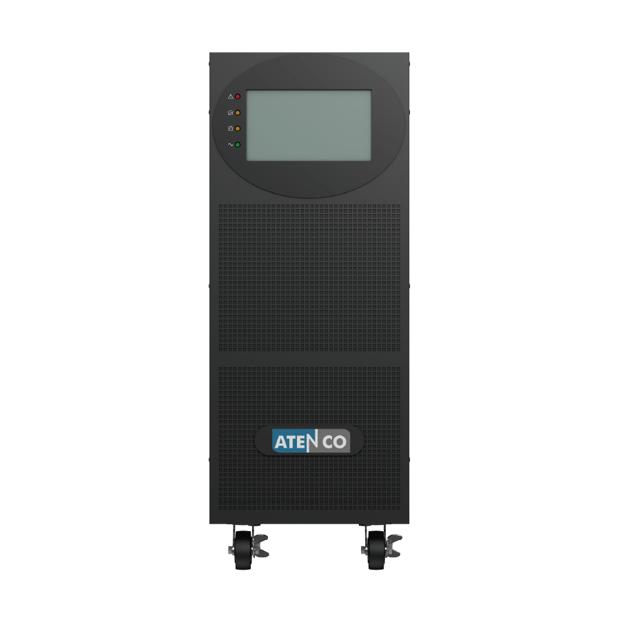
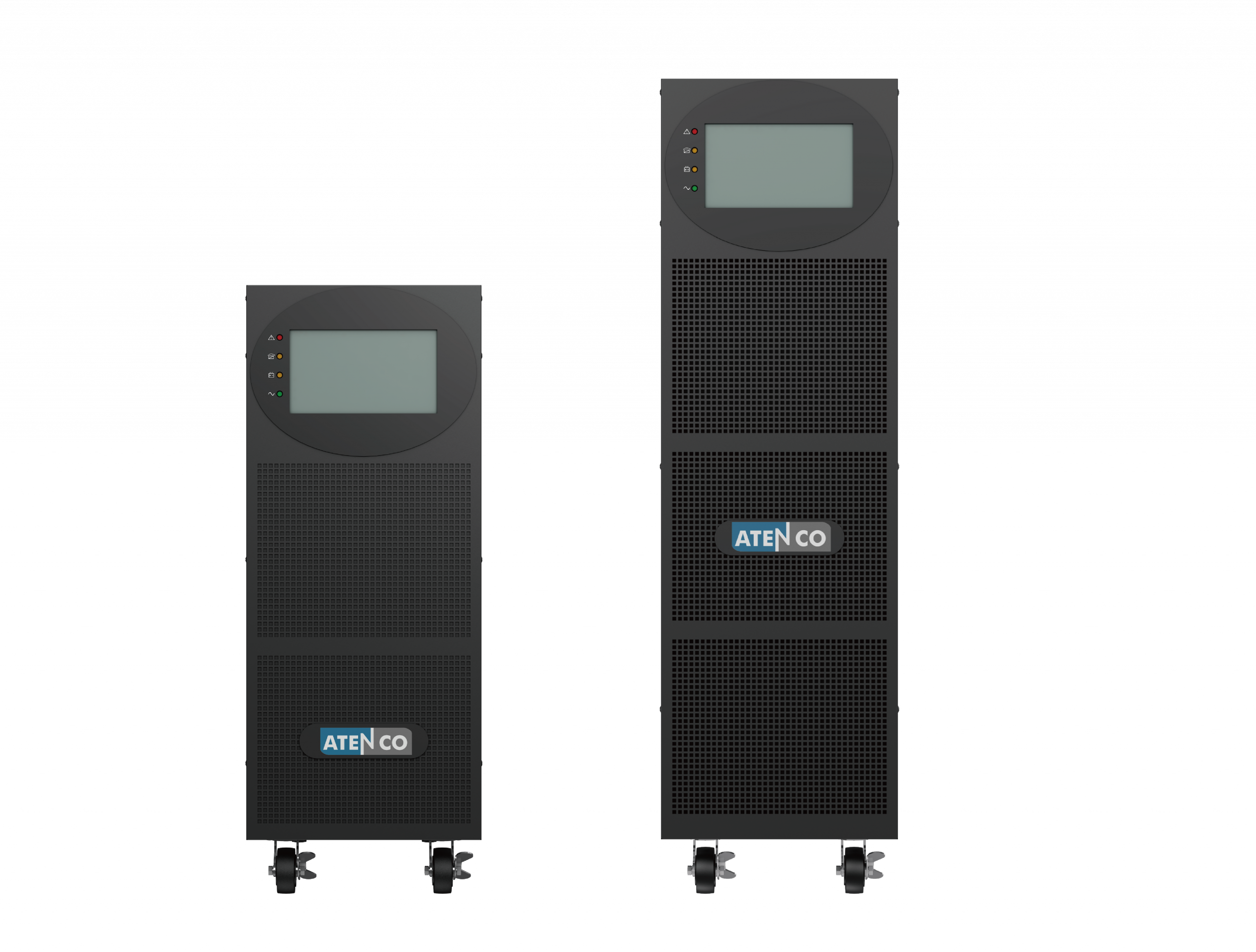
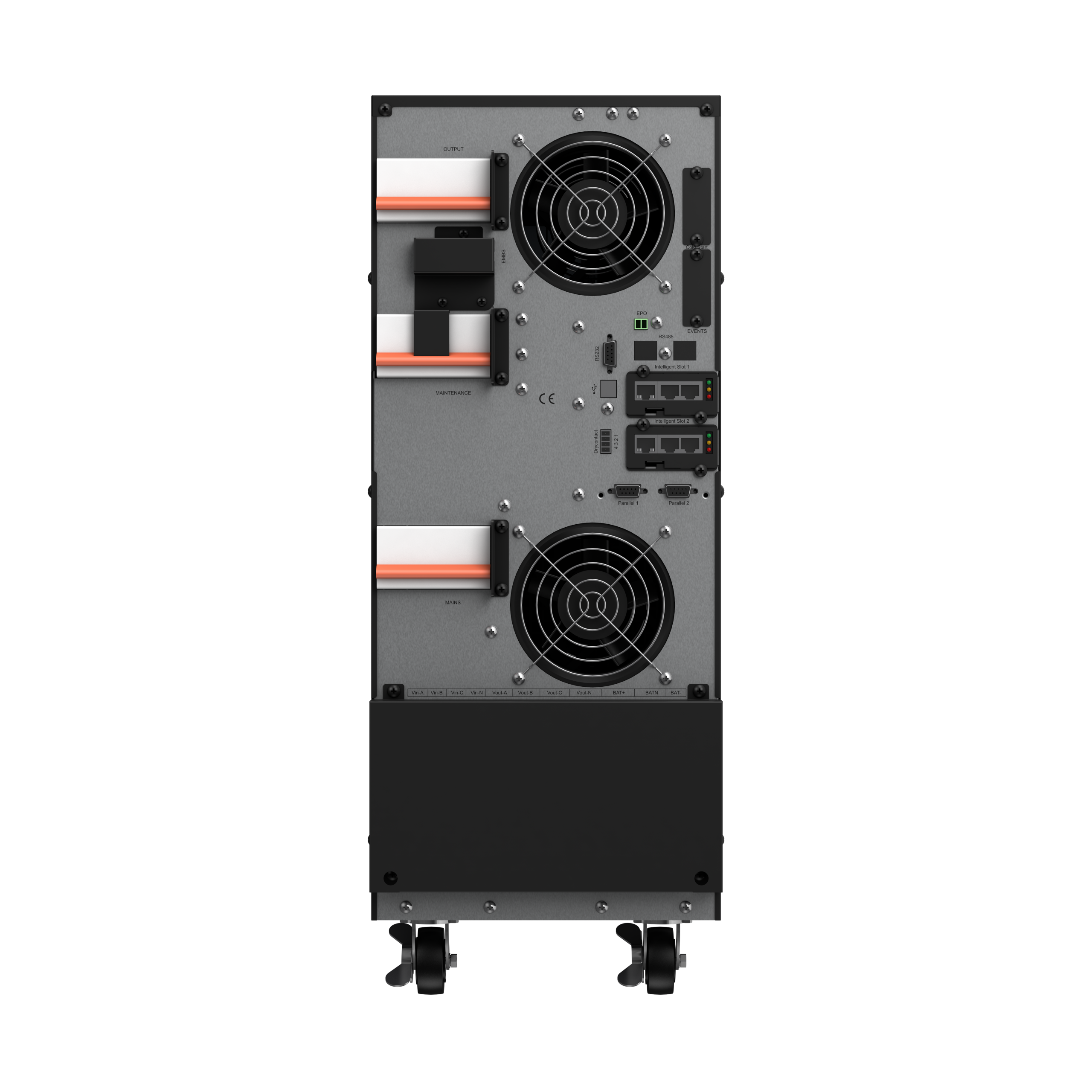
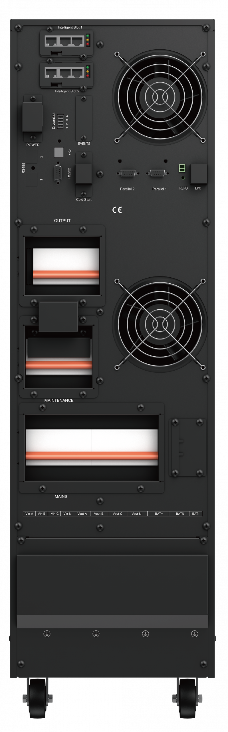
Engineered for 3:3 Mission-Critical Power
Transformer-less online double-conversion three-phase UPS architecture for data centers, industrial automation, healthcare facility IT, telecom and critical infrastructure requiring regulated three-phase output.
3-Phase Input / 3-Phase Output (3:3)
Accepts 380 / 400 / 415 Vac three-phase input and delivers regulated 380 / 400 / 415 Vac three-phase output with ±1% voltage regulation for data-center IT, industrial automation, telecom, healthcare facility IT and critical infrastructure loads.
Online Double-Conversion VFI
Transformer-less online double-conversion architecture with IGBT rectifier, IGBT inverter and DSP digital control provides regulated pure sine-wave output and 0 ms transfer time between online and battery operation. The internal static bypass transfers the load according to configured bypass limits and UPS operating conditions.
PF 1.0 Output & High Efficiency
Output PF 1.0 provides full usable kW capacity. Online efficiency reaches up to 94.5% by model, while input PF ≥0.99 and input THDi ≤3% at linear load help reduce upstream current demand and harmonic loading.
Wide Input Range & Generator Compatibility
The 10–30 kVA models support an operating input-voltage range of 208–478 Vac; the 40 kVA model supports 323–478 Vac, according to load and operating conditions. Supported input-frequency windows are 45–55 Hz for 50 Hz systems and 54–66 Hz for 60 Hz systems. The UPS can be used with a properly sized generator, subject to generator voltage regulation, frequency stability, load-step response and UPS charging-current settings.
Parallel Capacity & N+X Redundancy
Up to four matching TM33E units can be configured in parallel for capacity expansion or N+X redundancy, subject to model compatibility, approved parallel accessories, matching firmware and project commissioning.
7-inch TFT Touchscreen & Communication Options
A 7-inch TFT touchscreen provides local monitoring, operating status and configuration on selected models. Intelligent communication slots support approved SNMP and relay-card options for remote monitoring, event signalling and network-management or building-management integration, depending on model and configuration.
Expand Your System
Accessories for TM33E runtime extension, external VRLA battery systems, remote monitoring and parallel operation – available by model and configuration.
External Battery Cabinets
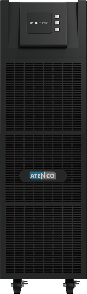
External TC-series VRLA battery cabinets support long-runtime TM33E configurations. Cabinet model, battery quantity, DC bus voltage, protection and cable sizing are selected according to UPS capacity, connected load, target backup time and project design.
Matched VRLA Battery Strings
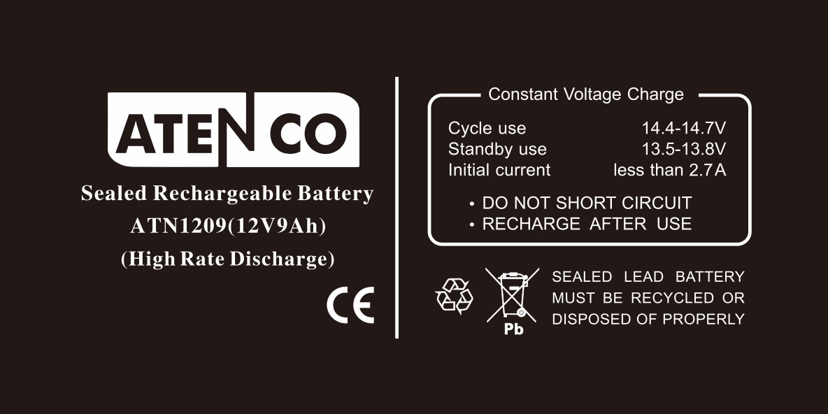
VRLA battery strings are selected according to TM33E capacity, DC bus configuration, connected load and target backup time. Batteries within the same string should have matching chemistry, voltage, capacity, age and performance characteristics; new and aged batteries should not be mixed within the same string.
SNMP Network Monitoring
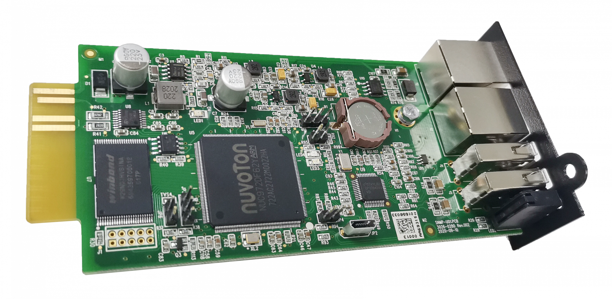
An optional compatible SNMP card enables remote UPS monitoring, web access, event alerts and supported NMS or building-management integration. Intelligent communication-slot and relay-card availability depends on TM33E model and configuration.
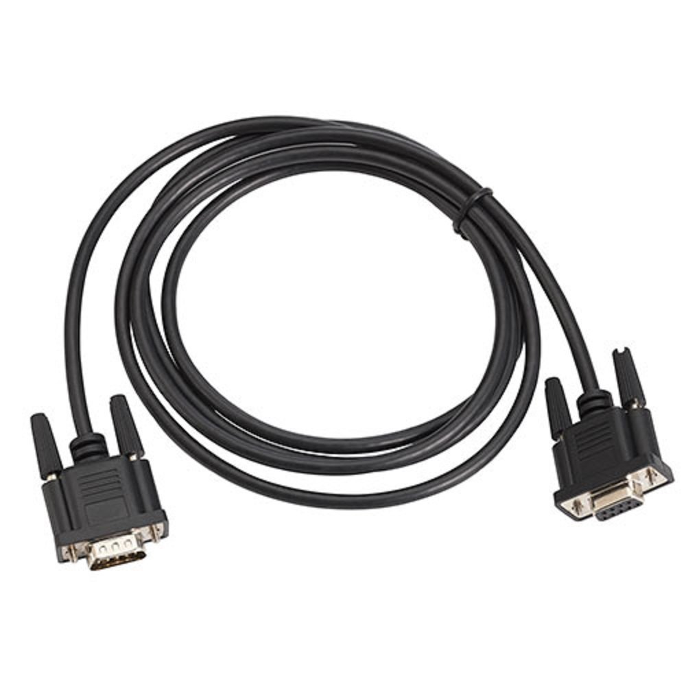
Parallel Kit & Cables
Approved parallel cables and accessories support up to four matching TM33E units for capacity expansion or N+X redundancy. Compatible ratings, firmware and system settings are required, and parallel installation and commissioning must follow the approved procedure.
Technical Details
Complete specifications for the TM33E 10–40 kVA three-phase tower UPS series.
| Specification | 10 kVA | 15 kVA | 20 kVA | 30 kVA | 40 kVA |
|---|---|---|---|---|---|
| Full Name | TM33E Three-Phase Tower Online UPS | ||||
| Topology | Online Double-Conversion (VFI), IGBT, DSP Control | ||||
| Phase | 3P–3P (Three Phase In / Three Phase Out) | ||||
| Form Factor | Tower | ||||
| Capacity | 10 kVA / 10kW | 15 kVA / 15kW | 20 kVA / 20kW | 30 kVA / 30kW | 40 kVA / 40kW |
| Output Power Factor | 1.0 (kW = kVA) | ||||
| Display | 7” Touchscreen TFT HMI | ||||
| Operating Modes | Normal (Online), ECO, Bypass, Battery, Maintenance | ||||
| Parallel | Up to 4 units (N+X redundancy, optional parallel kit) | ||||
| Generator Compatible | Yes | ||||
| Standards | CE; IEC / EN 62040-1; IEC / EN 62040-2 (EMC); LVD by series | ||||
| Specification | 10 kVA | 15 kVA | 20 kVA | 30 kVA | 40 kVA |
|---|---|---|---|---|---|
| Nominal Input Voltage | 380 / 400 / 415 Vac (3Ph + N + PE) | ||||
| Input Voltage Range | 208–478 Vac | 323–478 Vac | |||
| Input Derating | 305–478 Vac full load; 208–304 Vac derated operation | 323–478 Vac operating range | |||
| Input PF | ≥0.99 | ||||
| Input THDi | ≤3% at 100% non-linear load | ||||
| Input Frequency | 45–55 Hz / 54–66 Hz auto-sensing | ||||
| Output Voltage | 380 / 400 / 415 Vac (3Ph + N + PE), ±1% regulation | ||||
| Output PF | 1.0 (kW = kVA) | ||||
| Output THDv | ≤2% linear / ≤5% non-linear | ||||
| Output Frequency | Synced to input in line mode; 50 / 60 Hz ±0.1 Hz in battery mode | ||||
| Transfer Time | 0 ms (AC-to-Battery); automatic bypass protection by operating condition | ||||
| Crest Factor | 3:1 | ||||
| Dynamic Voltage Transient | ≤±5% | ||||
| Efficiency, AC Mode | ≥93.5% | ≥94.5% | ≥94.5% | ≥93.5% | ≥93.5% |
| Efficiency, ECO Mode | Available for energy saving in stable utility conditions by model / configuration | ||||
| Bypass Breaker | 20 A | 32 A | 40 A | 63 A | 100 A |
| Specification | Details |
|---|---|
| Battery Type | 12 V VRLA lead-acid maintenance-free |
| Battery Configuration | Internal or external battery configuration by model |
| Internal Battery Models | S models with internal battery compartment by configuration |
| Long-Run Models | L models use external battery cabinets |
| DC Bus Voltage | Configured according to UPS capacity and battery design |
| Charger Current | Model-dependent; selected according to battery capacity and project sizing |
| External Battery Cabinets | TC-series external VRLA battery cabinets by project configuration |
| Battery Runtime | Sized according to load, battery capacity and target backup time |
| Battery Life | 3–5 years typical at 25 °C; actual life depends on ambient temperature, cycling, discharge depth and maintenance conditions |
For exact internal-battery counts, DC bus values, charger currents and external cabinet specifications, refer to the TM33E 10–40 kVA datasheet and the External Battery Cabinet Manual in the Downloads section, or contact ATENCO engineers for project sizing.
Physical – S Model / Internal Battery Configuration
| Specification | 10 kVA | 15 kVA | 20 kVA | 30 kVA | 40 kVA |
|---|---|---|---|---|---|
| Form Factor | Tower | ||||
| Dimensions (W×D×H) | 250×868×900mm | ||||
| Weight without batteries | 48 kg | 147 kg | 147 kg | 225 kg | 225 kg |
| Noise | <55dB | <58dB | <61dB | <64dB | |
| Colour | Black | ||||
Physical – L Model / External Battery Configuration
| Specification | 10 kVA | 15 kVA | 20 kVA | 30 kVA | 40 kVA |
|---|---|---|---|---|---|
| Form Factor | Tower | ||||
| Dimensions (W×D×H) | 250×868×900mm | ||||
| UPS weight without external battery cabinet | 42 kg | 45 kg | 45 kg | 66 kg | 73 kg |
| Noise | <55 dB | <58 dB | <61 dB | <64 dB | |
Cable Sizing (minimum cross-section)
| Cable | 10 kVA | 15 kVA | 20 kVA | 30 kVA | 40 kVA |
|---|---|---|---|---|---|
| AC Input | 4 mm² | 6 mm² | 8 mm² | 12 mm² | 16 mm² |
| AC Output | 4 mm² | 6 mm² | 8 mm² | 12 mm² | 16 mm² |
| DC Battery | 10 mm² | 16 mm² | 20 mm² | 35 mm² | 35 mm² |
| Ground | 4 mm² | 6 mm² | 8 mm² | 8 mm² | 10 mm² |
Cable sizes are minimum reference values from the product specification. Final cable and breaker sizing must follow local electrical code, installation method, ambient temperature and project protection design.
| Interface | Details |
|---|---|
| USB | Standard USB for Muser4000 monitoring software (9600bps, 8N1) |
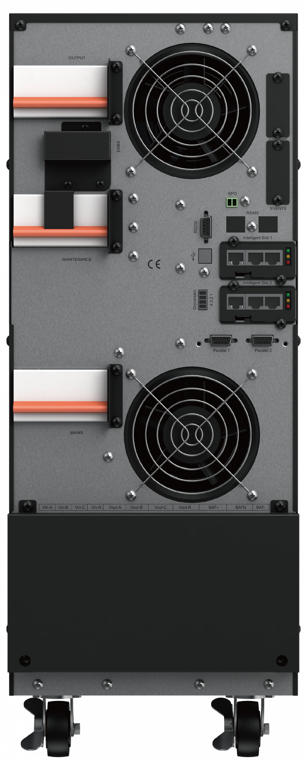
| RS-232 | DB9 Male serial (9600bps, 8N1) – Pin2=TXD, Pin3=RXD, Pin5=GND |
| RS-485 | RJ45 port for Modbus RTU and BMS / SCADA integration |
| Intelligent Slots | 2× slots – supports TM550 SNMP card and/or Relay card |
| Dry Contact Port | 4-pin: Battery Low, AC Fail, Turn Off UPS, Common GND |
| Parallel Ports | 2× parallel ports (ring topology, up to 4 units) |
| EPO / REPO | Emergency Power Off / Remote Emergency Power Off |
| Events Port | Events logging connector |
| BAT_T Port | RJ45 port for optional battery temperature sensor / dynamic charging |
| Maintenance Bypass | External maintenance bypass switch; internal / built-in bypass availability by model / configuration |
| Display | 7” colour touchscreen TFT HMI |
| Software | Muser4000 (USB/RS-232), SNMP_Management, SNMP_Protector |
| Optional | Parallel kit, Relay card, TM550 SNMP card, Temperature sensor, External bypass PDU |
Line Mode – Overload Capacity
| Load Level | Duration | Action |
|---|---|---|
| ≤110% | 60 minutes | Sustained |
| ≤125% | 10 minutes | Transfer to bypass |
| ≤150% | 1 minute | Transfer to bypass |
| ≥150% | Immediate | Transfer to bypass |
Battery Mode – Overload Capacity
| Load Level | Duration | Action |
|---|---|---|
| ≤110% | 10 minutes | Sustained on battery |
| ≤125% | 1 minute | Shutdown |
| ≤150% | 5 seconds | Shutdown |
| ≥150% | Immediate | Immediate shutdown |
Bypass Mode Note
| Condition | Behaviour |
|---|---|
| Load >95% | UPS remains on bypass and will not retransfer to inverter until load drops below 95%, according to bypass retransfer logic |
| Parameter | Specification |
|---|---|
| Operating Temperature | 0°C to 40°C (derate 12% per 5°C above 40°C, max 50°C) |
| Storage Temperature | −25°C to 55°C |
| Humidity | 0–95% RH non-condensing |
| Altitude Derating | 1500m=100%, 2000m=95%, 2500m=90%, 3000m=85%, 3500m=80%, 4000m=75% |
| Clearance | Min 100cm front, 80cm rear for ventilation & maintenance |
| Safety Standards | IEC / EN 62040-1; LVD by series |
| EMC Standards | IEC / EN 62040-2; IEC 61000-4-2 / -3 / -4 / -5 / -6 / -8 |
| Cooling | Forced air (fan) |
| Installation | Indoor use only |
| Applications | Data centers, telecom, healthcare facility IT, industrial automation, transportation, energy and critical infrastructure |
Ideal For
TM33E 10–40 kVA is designed for three-phase critical loads from 10 to 40 kW at PF 1.0, including small and medium data centers, industrial control systems, telecom network rooms, healthcare facility IT and commercial-building infrastructure requiring regulated three-phase output.
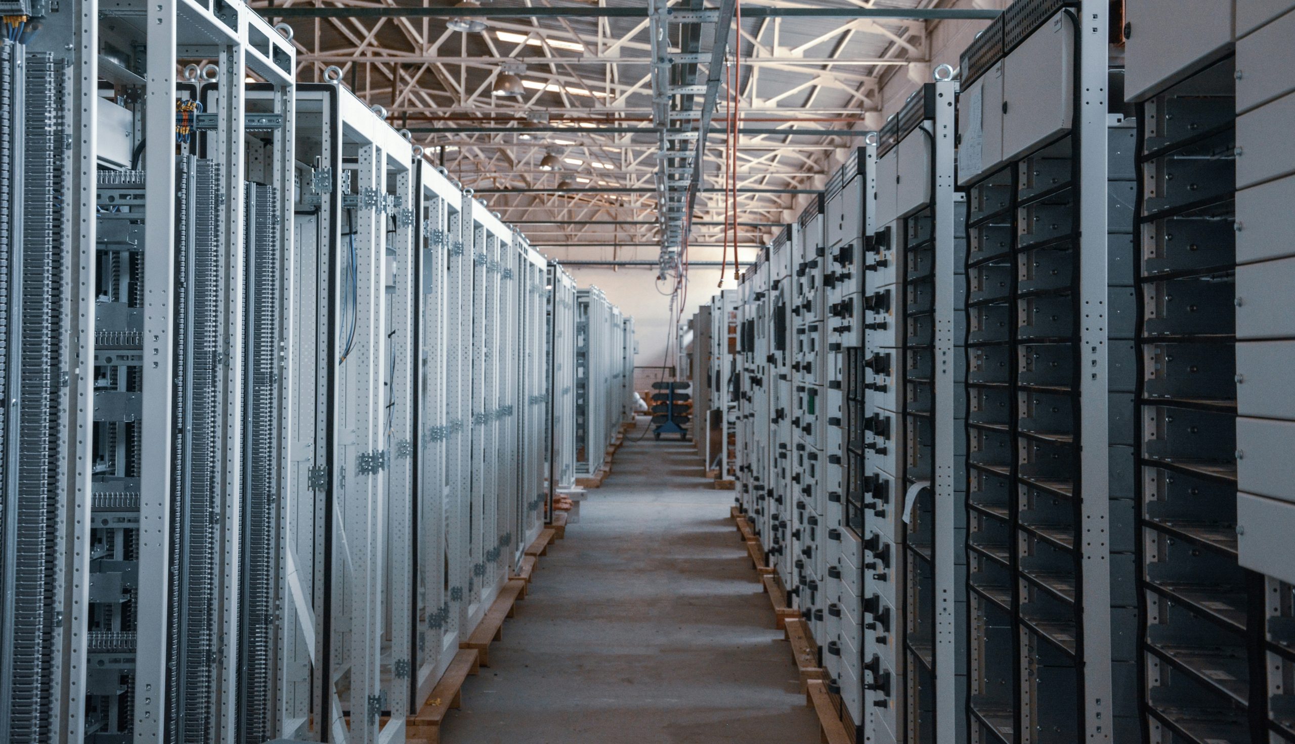
Small & Medium Data Centers
3:3 online UPS protection for three-phase server racks, PDUs, storage systems, network cores, firewalls and high-density IT loads in server rooms, small and medium data centers and edge-computing facilities.
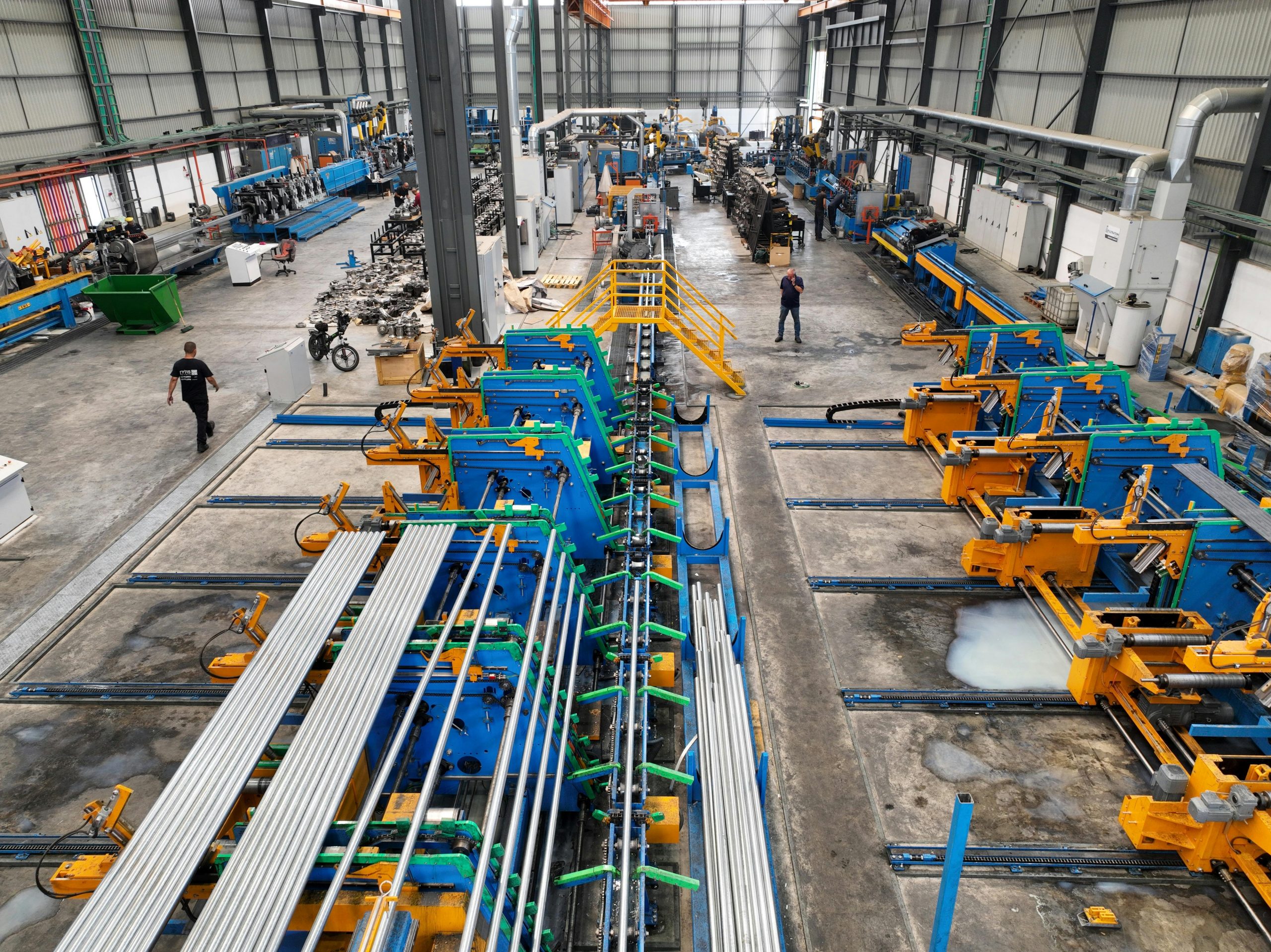
Industrial Automation & Process Control
Clean, regulated three-phase power for PLC panels, SCADA systems, industrial PCs, automation-control cabinets, instrumentation and process-control equipment supplied from plant three-phase distribution.
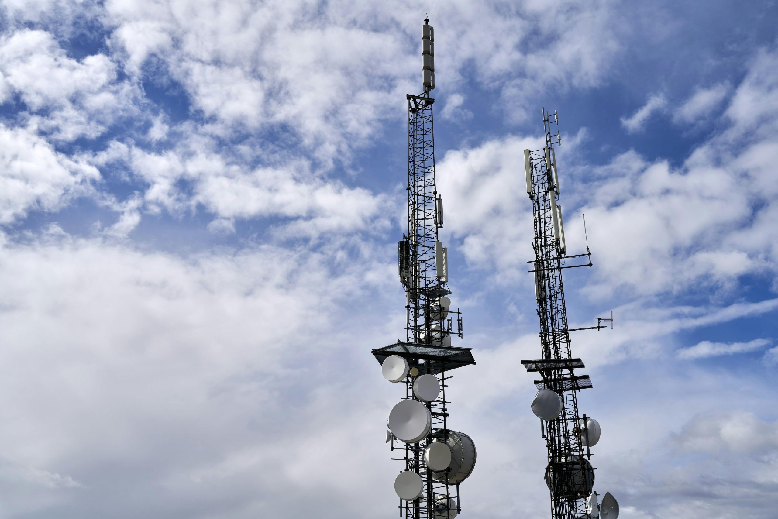
Telecom Switching & Network Nodes
Online three-phase UPS protection for telecom switching rooms, transmission equipment, access-network nodes, microwave systems and core-network infrastructure requiring continuous, regulated three-phase power.

Healthcare Facility IT & Laboratory Systems
Three-phase UPS protection for healthcare facility IT, laboratory instruments, clinical-monitoring infrastructure, imaging-support systems and technical rooms, subject to project electrical, certification, isolation and regulatory requirements.

Security Command & Control Rooms
Three-phase UPS support for centralized NVR and VMS server clusters, video-management workstations, access-control servers, monitoring walls and security command-room infrastructure.

Commercial Building Infrastructure
Regulated three-phase power for building network rooms, Building Management System panels, access-control platforms, security servers, tenant IT infrastructure and facility-control equipment in commercial, institutional and government buildings.
Need 3:1 Output, Rack Format or Higher Capacity?
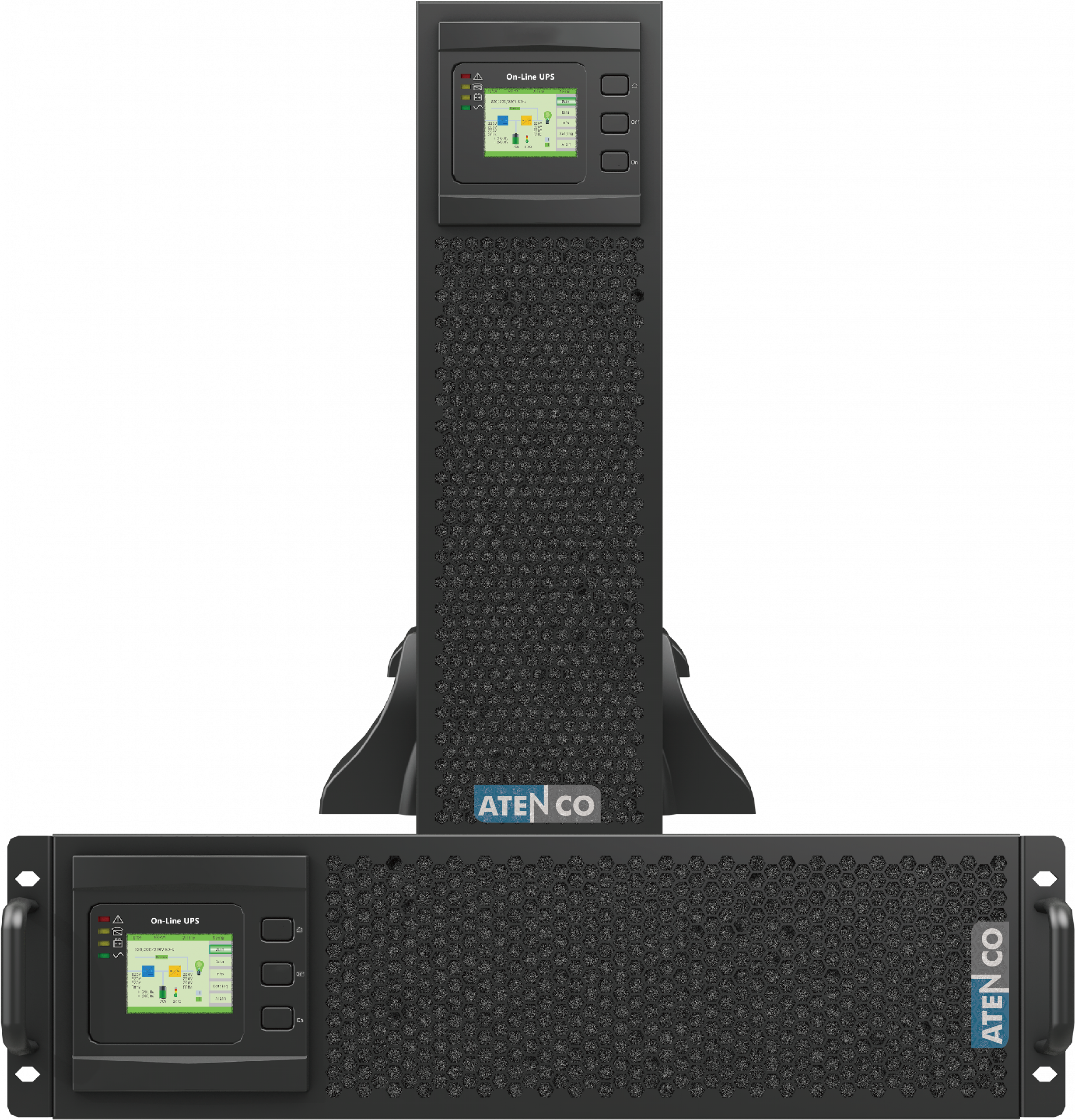
Compare TM33E 10–40 kVA with related ATENCO online UPS series for three-phase input with single-phase output, rack-mounted 3:3 installations, or higher-capacity three-phase power projects.
TM33E 10–40 kVA 3:3 UPS FAQ
Answers about TM33E three-phase input / three-phase output tower UPS architecture, 10–40 kVA capacity, PF 1.0 output, parallel operation, battery runtime and monitoring options.
What does TM33E mean?
What is the difference between TM33E 10–40 kVA and TM33E 50–200 kVA?
What is the difference between TM33E and TM31E?
What capacities are available for TM33E 10–40 kVA?
Can TM33E 10–40 kVA run on a generator?
Can TM33E 10–40 kVA be paralleled for redundancy?
What battery runtime options are available for TM33E 10–40 kVA?
What monitoring options does TM33E 10–40 kVA support?
Is TM33E 10–40 kVA transformer-based or transformer-less?
Which applications are not suitable for TM33E 10–40 kVA?
Size Your TM33E 10–40 kVA UPS Project
Share your three-phase load list, required backup time, redundancy plan, site voltage, generator details and monitoring requirements. ATENCO will recommend the appropriate 10, 15, 20, 30 or 40 kVA TM33E model, with the applicable internal-battery or external-battery arrangement for the selected model, TC-series battery cabinet, parallel topology and SNMP, RS-485 / Modbus RTU or relay-card options.
Send Project Requirements
Share the protected load in kW and kVA, target runtime, redundancy requirement, nominal site voltage, generator details and monitoring preferences such as SNMP, RS-485 / Modbus RTU, relay, NMS or building-management integration.
Receive UPS Selection & Sizing
ATENCO engineers recommend the suitable TM33E capacity and battery configuration, including the applicable internal-battery or external-battery arrangement, TC-series battery cabinet plan, parallel architecture and matching communication accessories.